









Do not turn a metal-wall concept into a universal backsplash dB claim
Metal can attenuate or reflect radio signals, but the effect depends on thickness, continuity, geometry, frequency, router location and the rest of the building. FCC material discussing building-entry loss notes significant attenuation from thick metal walls in a specific interference context. That does not establish a fixed loss for thin decorative metal tiles in a kitchen.
Explore this guide
Remove any expectation that one backsplash automatically blocks Wi-Fi by a stated number of decibels. A small metallic area between a router and device is different from a continuous metal enclosure or structural wall.
Create a before-and-after home measurement instead
Before installation, record router location, device location, Wi-Fi band and a few repeatable measurements in the areas that matter. After installation, repeat under similar conditions. Consumer signal readings can vary, so look for consistent changes rather than one dramatic number.
If performance changes, test router orientation or placement, access-point position and band before blaming the decorative wall alone. Keep the metal product construction and covered area in the record.
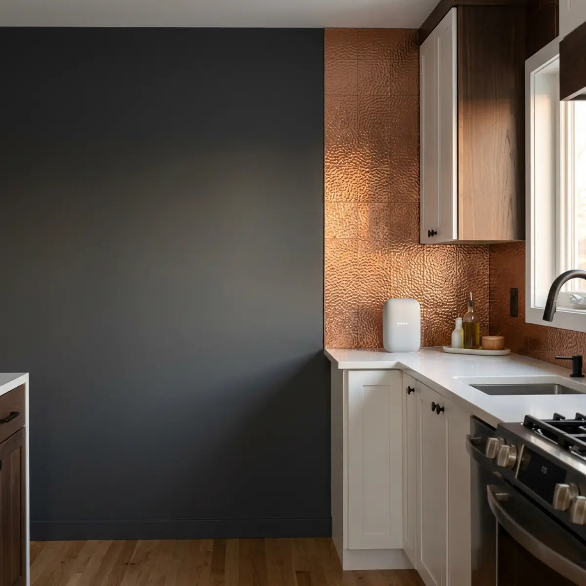
You finally install that stunning metallic backsplash. The kitchen looks incredible. Then, you plug in your smart coffee maker, and the WiFi drops. A familiar anxiety sets in. Did you just glue a giant signal-blocking shield to your kitchen wall?
We hear this specific concern constantly. Modern kitchens are packed with connected devices. From smart refrigerators to voice assistants, your home network is working overtime in this space. Homeowners worry that adding metallic peel-and-stick tiles will instantly sever these connections.
The modern culinary space is no longer just a place to prepare meals; it is a highly integrated technological hub. Today’s smart homes rely on a delicate invisible web of radio frequencies to automate lighting, monitor cooking temperatures, stream high-definition recipes, and even manage grocery inventories directly from the refrigerator door. When you introduce a new, potentially conductive material into this delicate ecosystem, the apprehension is entirely justified. Radio frequency (RF) dynamics are complex, and the aesthetic appeal of a shiny new backsplash shouldn't come at the cost of your digital convenience.
Rather than claiming a universal Wi-Fi effect for a broad material category, use the exact tile construction and a repeatable before-and-after check in the home where it will be installed.
Metallic-looking finishes vary from printed vinyl to products that include conductive layers, so appearance alone cannot predict radio behavior. Router placement, walls, appliances, covered area and an already-marginal connection can all change the result.
If Wi-Fi performance matters, record several observations before and after the environmental change: RSSI from the same location, latency over repeated checks, throughput where relevant, and whether the actual smart device remains stable. Keep the measurements separate instead of collapsing them into a proprietary score.
Immediate Takeaways for the Connected Kitchen
Here are the key points to understand immediately:
-
•
Material Matters: Metallic-looking tiles vary widely by material and backing. Many are just vinyl.
-
•
Band Differences: 2.4 GHz signals generally tolerate obstacles better than 5 GHz, but face more appliance congestion.
-
•
Layout Dominates: Router or mesh-node placement matters significantly more than the backsplash in most kitchens.
This guide explains how to make a repeatable home network record and how to troubleshoot placement without presenting invented lab results or promising uninterrupted connectivity.
The Myth
"Anything that looks like metal will instantly create a Faraday cage in my kitchen and block all my wireless devices."
The Reality
Metallic-looking does not always mean signal-blocking. Unless a surface is thick, continuous solid metal wrapping a device entirely, localized reflection rarely causes total network failure.

Do metallic peel-and-stick tiles actually interfere with WiFi?
Ever worried a shiny new kitchen wall will turn into a signal-blocking fortress?
This section unpacks the exact data on how metallic finishes impact your router's reach, separating unfounded fear from measurable science.
Metallic peel-and-stick tiles rarely act as total signal blockers. A standard kitchen backsplash is relatively small. It does not create a full enclosure around your devices.
To understand this, we need to look at how a true Faraday cage operates. A Faraday cage requires a continuous enclosure of conductive material designed to block external static and non-static electric fields. For a kitchen backsplash to achieve this level of isolation, the metal would need to cover the walls, the ceiling, the floor, and seamlessly wrap around the smart device itself. A standard 18-inch high strip of tile between your countertops and upper cabinets simply lacks the surface area and geometry to capture and neutralize all incoming radio waves.
However, metal is conductive. True metallic surfaces can reflect or absorb radio frequency (RF) waves. The question is not whether interference exists, but whether it disrupts your daily life.
When an RF wave hits a conductive surface, three things can happen: transmission, absorption, or reflection. With true solid metal, transmission is nearly zero. Absorption is minimal. The primary action is reflection. The waves bounce off the metallic face like light bouncing off a mirror. This creates a phenomenon known as "multipath interference." The original signal and the reflected signal arrive at the smart device's antenna at slightly different times, potentially confusing the receiver. Modern WiFi protocols (like 802.11ac and 802.11ax) actually use multiple antennas to harness multipath reflections to their advantage, but older, cheaper smart plugs might struggle to decode the overlapping data streams.
To evaluate a possible Wi-Fi change, use repeatable before-and-after observations: router and device location, band, test method and several readings. This is a home troubleshooting record, not a standardized laboratory evaluation.
A Before-and-After Wi-Fi Record
Tired of guessing if a new decor choice is ruining your connection?
This section separates measurements that can be repeated at home from claims that would require controlled RF testing.
For a home comparison, keep the device, measurement location, router configuration and test method as consistent as practical. Record RSSI, latency and throughput separately and repeat measurements because normal network traffic and radio conditions vary.
A before-and-after signal record can compare network behavior before and after an environmental change. Phone signal bars are coarse indicators, so use a consistent tool and repeated measurements without presenting the record as a validated quantitative baseline.
Measurements to track separately:
- RSSI (Received Signal Strength Indicator): The estimated power level of a received wireless signal, measured in decibels (dBm). Closer to zero is better.
- Throughput: The actual download and upload speeds achieved.
- Latency: The time it takes for data to travel to a server and back, measured in milliseconds (ms).
- Packet Loss: The percentage of data packets that fail to reach their destination.
Pro-Tip: Why RSSI in dBm is Crucial
RSSI is more useful than a signal-bar icon for relative comparison, but there is no single dBm threshold that predicts whether every device will work. Record repeated readings from the same location and pair them with the actual device behavior.
Understanding Tile Materials
Confused by terms like "brushed aluminum" and "metallic finish"?
This section reveals the actual material composition of popular tiles, preventing you from worrying about fake metal.
A common misconception is that all shiny tiles contain metal. In reality, the material composition varies wildly. You must look past the aesthetic descriptor and examine the engineering specifications of the product you are about to adhere to your walls.
A metallic appearance does not establish electrical conductivity. Some decorative finishes are nonconductive prints while others include conductive foil or metal layers; use the exact product construction instead of inferring RF behavior from the look.
Products that include a real aluminum or other conductive face can interact with radio waves, but the effect depends on layer continuity, thickness, covered area, orientation and the rest of the room. Do not infer a numeric signal loss from the material name alone.
Material composition can influence radio propagation, but a named composite product is not a quantitative baseline for Wi-Fi performance. Use the exact construction and covered area, then measure the actual home network if signal behavior matters.
Durability and wireless performance are separate questions. Use product-specific care, exposure and installation documentation for the wall finish, and use network measurements only to evaluate network behavior.
Do not assign a universal RF risk tier from a broad material label. Verify whether the exact product contains a conductive layer, note the covered area and signal path, and use before-and-after measurements when network performance matters.
How to Build a Repeatable Home Comparison Without Invented Test Data
Stickwoll is not presenting the numbers in this section as laboratory or field-test results. To evaluate a specific home, create your own record with the actual router, wall, tile sample or finished installation and devices that matter.
Keep the router configuration and measurement location fixed. Take several RSSI readings rather than one screenshot, run repeated latency checks, and note throughput only when it matters to the device. Record time and obvious changes in network load so a normal fluctuation is not blamed on the wall finish.
Compare the distribution of observations rather than using a single pass/fail dBm threshold. A measurable change does not automatically mean a smart plug, speaker or phone will fail, while an already weak connection may be sensitive to a smaller change.
If you need product-specific RF attenuation data, use documentation for the exact construction or controlled testing. A decorative article cannot substitute a hypothetical 15-square-foot installation and invented before/after table for that evidence.
Why do smart plugs and speakers fail near kitchen backsplashes?
If the tile isn't killing the WiFi, why does the smart plug keep blinking offline?
This section diagnoses the hidden, invisible forces in your kitchen that are actually dropping your connections.
If a device becomes unreliable after a kitchen change, investigate more than one variable before assigning the cause to the backsplash.
The answer lies in compounding variables. A kitchen is an exceptionally hostile environment for radio frequencies. It is dense with water, metal, electrical currents, and competing signals. When you add a metallic backsplash to an already weak layout, you tip the scale from "barely working" to "disconnected." The tile is rarely the primary offender; it is simply the catalyst that reveals an underlying network architecture problem.
Check the entire signal path: router placement, walls, appliances, competing networks, device location and the exact backsplash construction.
A Kitchen Connectivity Troubleshooting Checklist
Overwhelmed by multiple devices failing at random times?
This section introduces a systematic framework to isolate the exact cause of your smart home connectivity issues.
Use the checklist to organize possible causes, not to rank them with a proprietary score. Change one variable at a time where practical and repeat the same observation.
Diagnostic Visualization: Signal Path Risk
(Living Room)
(RF Shield)
(On Tile)
This diagram is illustrative only. Obstructions can change a radio path, but it does not assign a percentage loss to a refrigerator, wall or tile.
Factors to check:
-
1
Appliance Shielding: Refrigerator compressors, massive metal oven bodies, and dishwashers physically blocking the line-of-sight.
-
2
Microwave Interference: Magnetrons leaking massive amounts of RF noise directly into the 2.4 GHz spectrum during operation.
-
3
Band Congestion: Too many low-bandwidth IoT devices fighting for airtime on the same narrow WiFi channel.
-
4
Router Placement: The primary signal source is too distant, or buried under a desk, rendering its broadcast inherently weak before it even reaches the kitchen.
-
5
Tile Material: Reflective metallic surfaces causing localized multipath interference, confusing the device's receiver right at the wall surface.
The Problem with the 2.4 GHz Band
Why do cheap smart plugs struggle more than expensive laptops?
This section explains the crowded highway of the 2.4 GHz spectrum and why your smart home devices are prone to traffic jams.
Most smart plugs, light switches, and kitchen appliances operate exclusively on the 2.4 GHz WiFi band. Manufacturers prefer this band because the hardware chips are incredibly cheap to produce, and the physical properties of a 2.4 GHz wave allow it to travel much further than higher frequencies.
The 2.4 GHz band is excellent at penetrating solid objects like walls and cabinets because its physical wavelength is roughly 4.9 inches long. This size allows it to diffract around smaller obstacles. However, it is a narrow, incredibly crowded highway. There are only 3 non-overlapping channels (1, 6, and 11) available in this spectrum in North America.
Your WiFi router, Bluetooth devices, baby monitors, cordless phones, and Zigbee smart hubs all share this same general frequency range. When evaluating total network capacity, the baseline metric shifts from raw speed to spectral efficiency. It doesn't matter if your smart plug only needs 1 Mbps to turn on a light if the channel is so clogged with noise that the plug can never get a clear moment to transmit that tiny packet of data.
The Connectivity Standards Alliance, which oversees protocols like Zigbee and the new Matter standard, actively plans for this coexistence by enforcing strict transmission rules. However, a kitchen concentrates too many competing signals into a small footprint.
When you add a metallic backsplash, you might reflect some of this chaotic noise back into the room rather than letting it bleed harmlessly through the wall. This localized reflection can confuse cheaper smart home radios that lack advanced signal processing capabilities.
The Microwave Oven Effect
Does your music stop playing every time you heat up leftovers?
This section uncovers the massive, invisible disruption caused by standard microwave ovens.
A common misconception is that a router is the only thing broadcasting in your house. The reality is that your kitchen houses one of the most powerful localized radio transmitters imaginable: your microwave oven.
Microwave ovens operate near 2.45 GHz, close to part of the 2.4 GHz Wi-Fi band. Under some conditions, Wi-Fi performance can change while a nearby microwave is operating, so timing is one variable worth observing.
Do not infer a microwave fault or a leakage percentage from a Wi-Fi symptom. If connectivity changes only during normal microwave use, compare the same device before, during and after use; never run a microwave empty just to create a network test.
If the problem coincides with normal microwave use, note that timing and compare another supported band or device where practical. That can narrow the troubleshooting path, but it does not prove a single cause by itself.
Appliance Shielding and Water Pipes
Are large appliances acting like invisible walls in your kitchen layout?
This section details how stainless steel refrigerators and dense plumbing destroy WiFi signals before they even reach the tile.
Water, plumbing, ductwork and other building materials can change radio propagation. Their effect depends on geometry, material and the signal path; do not treat one pipe or wall cavity as a universal Wi-Fi blocker.
Large metal appliances can shadow or reflect a radio path, especially when they sit directly between a router and device. The size of the effect is layout-specific, so compare readings around the appliance rather than calling it impenetrable.
If your router is in the living room, and the signal must pass through the refrigerator to reach the smart plug on the backsplash, the signal is already critically weak. It is arriving at the plug through diffraction—bending weakly around the edges of the fridge.
Appliance placement, metal surfaces and other obstructions can affect both heat planning and radio paths, but these are separate questions. Check appliance clearances from the relevant instructions and test network behavior independently.
If a weak signal finally bypasses the fridge, hits the backsplash, and reflects off a metallic tile, that final reflection might be the breaking point. The tile was just the final straw in a long chain of physical obstacles.
Troubleshooting Kitchen Connectivity
Ready to fix the exact problem plaguing your kitchen devices?
This section provides an actionable matrix to diagnose and resolve specific connectivity symptoms.
Use this troubleshooting table to organize possible causes of a network change. Treat each observation as evidence to investigate rather than a standardized test result.
| Observed Symptom | Most Likely Cause | How to Test It | Recommended Fix |
|---|---|---|---|
| Drops during cooking | Microwave 2.4 GHz leakage | Run microwave for 2 minutes while pinging device constantly | Move device away from microwave; use 5 GHz if possible. |
| Total dead zone near fridge | Appliance RF shielding | Check RSSI directly behind vs. to the side of fridge | Relocate smart plug or adjust mesh node placement. |
| Random evening drops | 2.4 GHz band congestion | Check router app for channel interference during peak hours | Change router 2.4 GHz channel to 1, 6, or 11 manually. |
| Weak signal everywhere | Poor primary router location | Walk room with WiFi analyzer app and map the grid | Move router centrally or add a dedicated kitchen mesh node. |
| Device fails near tile only | Multipath reflection from metal | Place device on an extension cord 2 feet out from the wall | Swap out device for one with a better internal antenna. |
Pre-installation connectivity checklist
Record router and device locations, note major obstructions, capture repeated baseline readings, and test the devices that matter. This checklist does not calculate a Low/Moderate/High risk score or approve an installation.

How to Create a Repeatable Before-and-After Wi-Fi Record
Hesitant to commit a weekend to a project that might ruin your connection?
Use these steps to make a repeatable home comparison before and after a change. They reduce uncertainty but do not certify a material or network.
You can reduce uncertainty by recording the actual network before and after a material or layout change. This is a home troubleshooting comparison, not a replication of a Stickwoll laboratory method or a universal RF test.
Record your existing network conditions before installation if Wi-Fi performance matters. Repeat the same observations afterward; this establishes a practical comparison, not a laboratory baseline or guarantee.
Here is a repeatable home-check workflow.
Step 1: Map Your Baseline Network Health
Do you actually know how strong your current WiFi is?
This section explains how to grab the vital statistics of your network before making any changes.
Before introducing any new materials, you must understand your current baseline. A standard internet speed test alone is not enough. Speed fluctuates based on your ISP, current neighborhood traffic, and backend routing. You need to measure the raw, physical signal power radiating from your router to the wall.
Download a free WiFi analyzer app on your smartphone. We recommend apps like WiFiman by Ubiquiti or NetSpot, which provide granular data rather than simplified graphics.
-
1
Mark one measurement position and hold the device in the same orientation for each comparison. Avoid changing your own position or nearby objects between readings where practical.
-
2
Record the RSSI: Note the dBm number for both your 2.4 GHz and 5 GHz networks. Watch it for 30 seconds to establish a stable average, as the number will bounce slightly.
-
3
Run repeated latency checks with the same tool and endpoint where practical. Jitter or latency can change for many reasons, so do not attribute one high reading to the wall finish by itself.
Keep these observations as the starting point for the before-and-after comparison.
Wi-Fi Comparison Worksheet
Step 2: Optional Conductive-Surface Demonstration (Not a Tile Proxy)
Want to simulate a metal wall without buying a single tile?
This section reveals a clever, zero-cost trick to stress-test your kitchen's RF environment.
If you want to see how a larger conductive surface can change readings, you can compare the same measurement location with and without a temporary piece of foil. Keep foil away from outlets, switches, heat sources and appliances, and do not treat this demonstration as a prediction for a specific tile.
A continuous foil sheet is electrically and geometrically different from a composite tile assembly. The useful observation is simply whether the network reading changes under a deliberately different condition; the magnitude cannot be transferred to another material.
Do not call the foil condition a worst-case test or a validated proxy. Product-specific RF behavior requires the exact construction and controlled measurement.
A device remaining connected during the foil demonstration does not approve a future installation. Re-check the actual network after installation and troubleshoot any persistent change.
Surface preparation and Wi-Fi troubleshooting are separate tasks. Follow the tile instructions for wall preparation, and use repeatable network measurements for radio performance rather than borrowing an adhesion test as a network-performance baseline.
Step 3: Compare the Repeated Observations
Ready to see if your network can handle the interference?
This section guides you through the final measurements to determine if your devices will survive the upgrade.
If you perform the optional conductive-surface demonstration or have a documented product sample, repeat observations from the same marked locations. Treat the result as a comparison of those two conditions, not as a prediction for a different tile assembly.
-
1
Take repeated RSSI readings from the same marked position and device orientation. Record the values and normal variation instead of relying on a fixed 30-second averaging rule.
-
2
Compare the observations directly. Keep baseline and second-condition RSSI, latency and device behavior as separate measurements rather than turning them into an before-and-after score or pass/fail number.
-
3
Test the actual smart devices in their normal locations and normal use. Note disconnects, delayed responses or recovery behavior without treating one successful command as proof that a future installation is safe for the network.
Do not use a universal dBm cutoff as an installation approval. Compare repeated readings, test the devices that matter in their real locations, and investigate a meaningful or persistent degradation before covering the full wall.
If devices repeatedly drop offline or latency changes materially, stop treating the wall finish as the only suspect. Re-check router placement, congestion, obstructions and device behavior before making a full-wall change.
Pre-Installation Readiness Checklist
Click the items to cross them off as you prepare your kitchen network.
A Note on Surface Durability and Seams
Did you know the physical layout of your tiles impacts signal reflection?
This section explains why continuous metal seams act differently than individual, broken tile patterns.
The way you install the tile can subtly impact RF reflection. A massive, unbroken sheet of metal is a highly efficient signal reflector. It acts like a giant, unified antenna mirroring back the localized energy.
Individual peel-and-stick tiles break up this conductive plane. Grout lines, even fake ones embedded in the tile's design, create microscopic gaps. These gaps disrupt the continuous flow of electrical currents across the surface, slightly reducing the shield effect. The more segmented the metallic face, the less efficient it becomes at creating unified multipath interference.
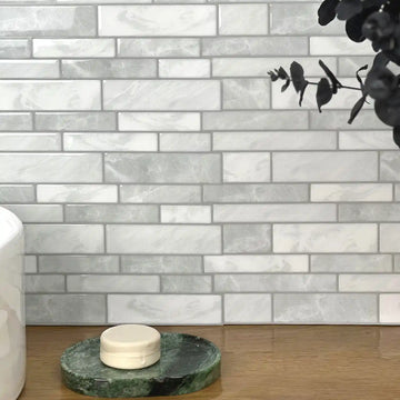
A patterned metallic-look tile such as Alloy Marble Hex should not be assigned an RF advantage from appearance alone. Conductivity, backing, layer continuity, covered area and geometry all matter, and decorative gaps do not prove lower attenuation than a solid metal sheet without testing the exact constructions.
Furthermore, how the seams lock together matters both aesthetically and practically. Tightly interlocked metallic faces behave differently than straight-edged tiles with wide, non-conductive gaps.
Seam geometry affects appearance and the continuity of the installed surface, but it does not provide a validated Wi-Fi metric. Plan seams for the product system and measure network behavior directly if needed.
Router placement and mesh node strategies for kitchens
Is your router fighting a losing battle against your kitchen appliances?
This section covers practical router and mesh-node placement checks that you can validate in your own home.
If your before-and-after check revealed a critical failure, do not abandon your design plans. The solution is rarely changing the tile. The solution is almost always fixing your network geometry.
You must engineer the environment to bypass the physical and electromagnetic obstacles blocking your path. Networking is a science of layout, not just raw broadcasting power.
The Line-of-Sight Rule
Why does moving a router six inches drastically improve your speed?
This section explains the critical importance of visual clearance between your router and your smart devices.
Radio frequencies at 2.4 GHz and 5 GHz behave somewhat like light. They travel best when they can "see" the destination. While they can punch through drywall, every obstacle degrades the wave's amplitude (strength).
If you draw a straight line from your router's antennas to your kitchen smart plug, what does that physical line pass through?
If the line passes through a dense couch, two drywall corners laced with copper wiring, and the heavy compressor of a refrigerator, the signal is exhausted by the time it reaches the backsplash. Adding a reflective tile is merely the coup de grâce.
You must clear the Fresnel Zone.
Fresnel Zone—the elliptical, three-dimensional area between a transmitter and receiver that must remain largely clear of solid obstacles for optimal signal transfer. It is not just a straight line; it is a football-shaped bubble of energy. If the bottom half of that bubble is clipping a metal desk, the entire signal suffers.
Moving a router away from the floor, dense furniture or large appliances can change coverage, but the size of any improvement is home-specific. Re-measure the same locations after repositioning instead of assuming a fixed 10–15 dBm gain.
Strategic Mesh Node Placement
Did you put your mesh node right next to the microwave?
This section highlights the most common mistake homeowners make when expanding their WiFi into the kitchen.
Many homeowners buy a mesh WiFi system (like Eero, Google Nest, or Orbi) to fix kitchen dead zones. A mesh system uses multiple broadcasting nodes to blanket the house in coverage by relaying the signal.
A common, fatal mistake is placing the kitchen node directly inside the interference zone. Many people place the node right next to the smart device that is failing.
If you place a mesh node on the kitchen counter, directly under the microwave, next to the metallic backsplash, and behind the fridge, you are suffocating the node itself. It cannot communicate effectively with the primary router via its wireless backhaul channel. A mesh node can only rebroadcast the signal it receives; if it receives garbage, it broadcasts garbage.
Mesh-node placement depends on the home layout, backhaul, router capabilities and interference. Test candidate positions rather than prescribing one hallway location as a universal rule.
This placement allows the node to maintain a clean, high-speed connection to the primary router in the living room. It then blasts a strong, localized signal directly into the kitchen through the doorway, bypassing the heavy wall interference entirely.
Hardwiring High-Bandwidth Devices
Are your streaming devices hogging the airwaves meant for your smart home?
This section explains how offloading heavy traffic stabilizes your entire wireless network.
If your 2.4 GHz band is severely congested, you need to clear the airwaves. Modern routers use a technology called MU-MIMO (Multi-User, Multiple-Input, Multiple-Output), but even that has limitations when dozens of devices are shouting simultaneously.
Smart plugs and voice assistants cannot be hardwired. They rely entirely on WiFi. However, your smart TV, gaming console, and desktop computer usually have Ethernet ports.
By plugging heavy-bandwidth devices directly into the router with an Ethernet cable, you instantly remove massive amounts of RF traffic from the air. A 4K video stream running over WiFi creates relentless spectral noise.
This frees up the spectrum. It allows the weaker, intermittent signals from your kitchen smart plugs to punch through the noise, even if they have to reflect off a new metallic backsplash. It creates breathing room in the digital environment.
Network congestion, router placement and building materials can all affect performance. Diagnose them separately; an article about cold walls or tile density is not a quantitative baseline for network traffic or radio attenuation.
Upgrading Legacy Devices
Is a five-year-old smart plug dragging down your brand-new router?
This section discusses when it is finally time to retire outdated tech that cannot handle modern interference.
Sometimes, the device itself is the weak link. Early-generation smart plugs featured tiny, inefficient internal antennas. They used outdated 802.11b/g WiFi chips that required longer transmission times and were easily confused by localized multipath interference (signals bouncing off metal walls).
Newer devices may use different radios, antennas or protocols such as Wi-Fi, Thread or Zigbee, but age alone does not predict RF performance. Compare the device specifications and behavior in the actual location.
If one device fails while others remain stable, test its placement, firmware, radio band and hardware before changing the backsplash. Replacing the device is one option only after the actual cause and cost are considered.
Material durability and Wi-Fi behavior are separate questions. Choose the wall finish from its documented surface, heat, moisture, cleaning and installation limits, then troubleshoot network performance with the actual router and devices.
Final Thoughts
Still feeling anxious about your upcoming kitchen upgrade?
This section summarizes the core takeaways, giving you the confidence to proceed with your renovation.
There is no universal Wi-Fi answer based on a metallic appearance alone. The exact layers, covered area, room geometry, router and device locations all matter, so compare the actual network if connectivity is important.
Do not assume the backsplash is either the main cause or a negligible variable. Router placement, appliances, neighboring networks, device hardware and the wall finish can interact, and a before-and-after comparison is the practical way to narrow the cause.
A before-and-after record gives you evidence from your own network without pretending to be a controlled RF study. If coverage is weak, test router elevation, placement away from dense obstructions, or a better mesh-node location and repeat the same measurements. A foil screen can demonstrate that metal can affect radio propagation, but it is not a quantitative proxy for the exact tile assembly.
A design choice and a reliable network can often coexist, but neither should be promised in advance. Validate the wall finish against its product documentation and validate connectivity with the devices in the actual room.
Frequently Asked Questions
Will foil-backed peel-and-stick tile block my cell phone signal?
Do not assume a backsplash has zero effect on cellular service. Cellular performance depends on band, exterior construction, indoor geometry, network conditions and the exact conductive material; compare the phone in the actual location if reception changes.
Do I need to buy a special router if I have metal tiles?
A metallic-looking backsplash does not by itself define a router requirement. If Wi-Fi changes, first check placement, band, congestion and device behavior; consider hardware changes only after identifying the actual limitation.
Can I install a smart switch directly into a metallic peel-and-stick tile?
Electrical work around conductive finishes must follow the switch or outlet instructions and applicable electrical code. Do not allow conductive material to contact energized terminals; use a qualified electrician when the installation is outside your competence or local rules require one.
Is it better to connect kitchen devices to 2.4 GHz or 5 GHz?
Use the band supported by the actual device and router. Many IoT products use 2.4 GHz, while some support other bands or protocols; test coverage in the intended location rather than applying one band rule to every kitchen device.
Sources and scope
- FCC 26-1 — Building Entry Loss and Metal-Wall Attenuation Context — FCC notes significant attenuation from thick metal walls in a wireless-interference context; not a test of decorative metal backsplash tiles or home Wi-Fi.



Leave a comment
This site is protected by hCaptcha and the hCaptcha Privacy Policy and Terms of Service apply.